Wavetable Synthesizer
PERCEPTIBLE SHIFTS IN TIMBRE THROUGH REAL-TIME WAVEFORM GENERATION AND MANIPULATION
This project came about through an interest in transformative sounds. Sound can evolve in a number of ways - through changes in pitch and melody, velocity, and timber. For example, a guitarist can switch to a new pedal to change the timbre of their instrument as they play, or a keyboard player can pick up a melody where a saxophonist left off. Likewise, sound synthesis allows a myriad of ways to change the timbre of a voice. In the traditional methods of synthesis such as subtractive or additive synthesis, waveform shape is indirectly controlled with various parameters. This waveform shape is what ultimately defines the timbre of the synthesizer.
Timbre
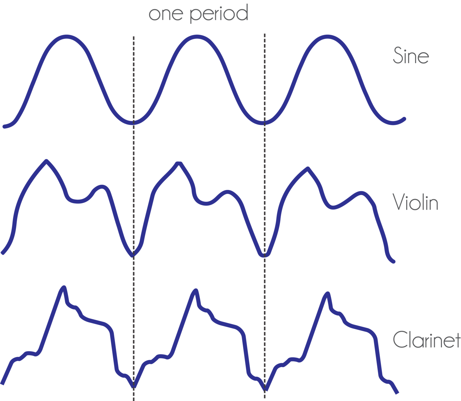
The waveforms in the figure to the right represent the same pitch and amplitude. But when played side by side, they would all sound distinctly different, despite being musically the same. By looking at one period of the waveform, one can see why - the sine is a pure tone, but the violin and clarinet both have waveforms that contain many other harmonics which richen the sound.
CREATIVE SYNTHESIS
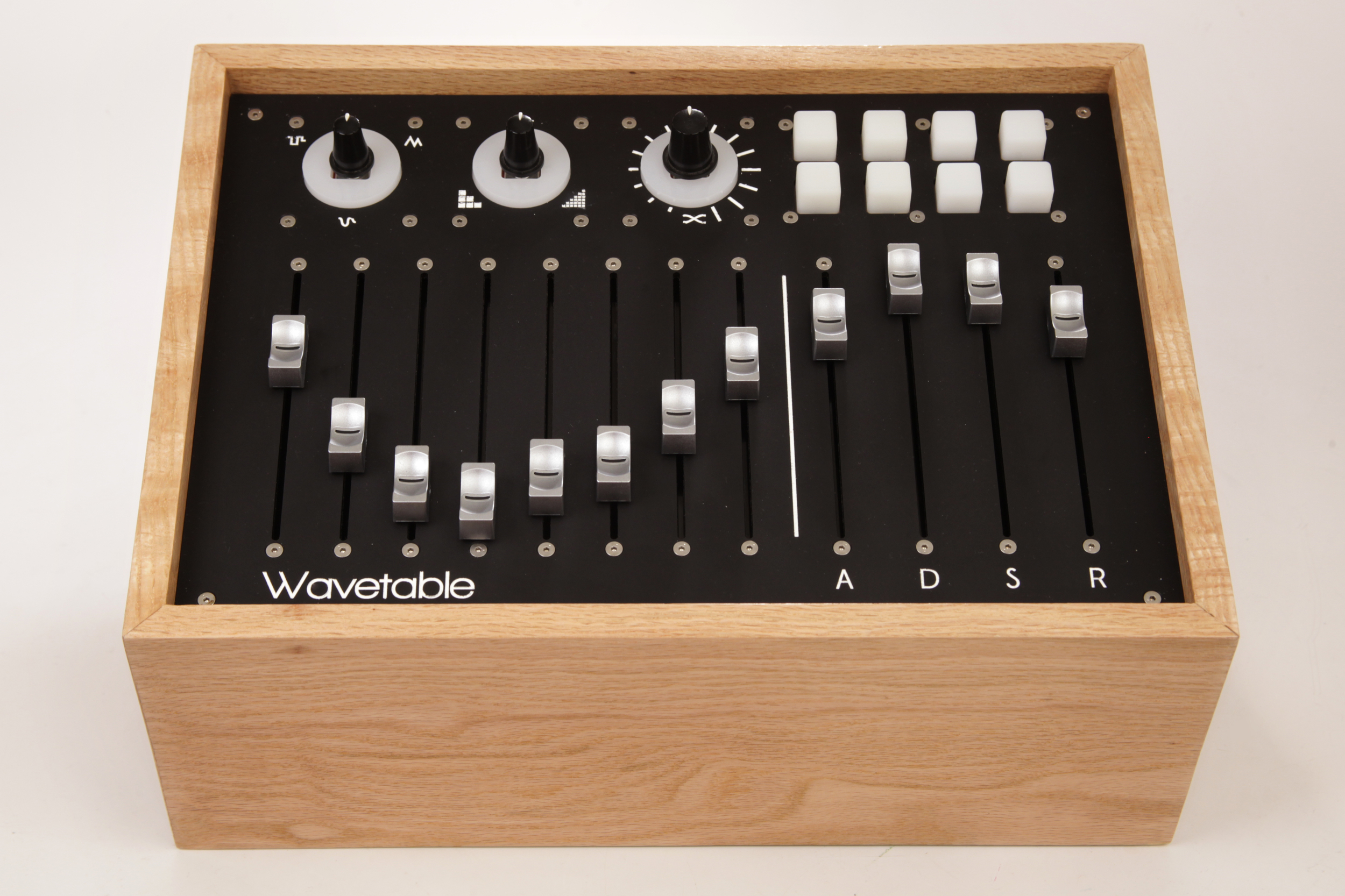
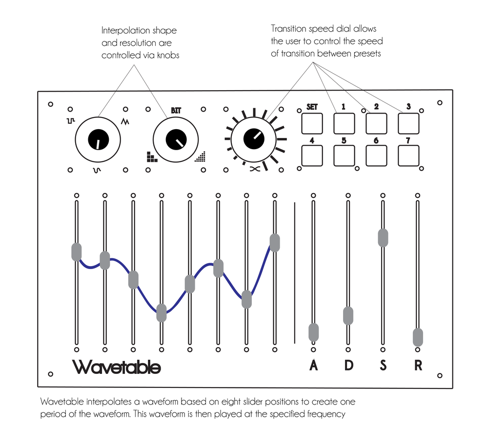 The Wavetable Synthesizer utilizes what I have dubbed “creative synthesis”. Instead of indirectly affecting waveform shape with envelopes, LFO’s, and oscillators, the Wavetable Synthesizer allows the user to directly control the waveform shape using 12 sliders and two knobs. Eight of the sliders control the overall shape of the wave (acting much like “attractors” on a line), while two knobs control how the points are interpolated (smooth, triangular, or square) and at what resolution (from fine to coarse). The four sliders labeled “A”, “D”, “S”, and “R” are used for attack, decay, sustain, and release respectively (more information on that here). Users can access saved waveforms with a bank of buttons, and when selected, can watch the controller transform automatically to these settings. The rightmost knob allows for control of the transition speed between presets.
THE IMPORTANCE OF TACTILE FEEDBACK AND PHYSICALITY
While this synthesizer could easily be limited to the software domain (and even thrive as an iPad app or Max for Live device), I truly value the connections one creates with physical objects. With a tangible object, the user can easily identify and adjust parameters that exist in our three dimensional world. On an iPad or computer screen, the interface is always predefined as a swipe or a click. This severely limits gestures - the basis of so much artistic expression. Specialized interfaces allow for idealized expressive control and intuitive interaction. They allow the computer producer a sense of musicality even with simple effects by allowing full use of the hands and even the body.
SYSTEM DIAGRAM
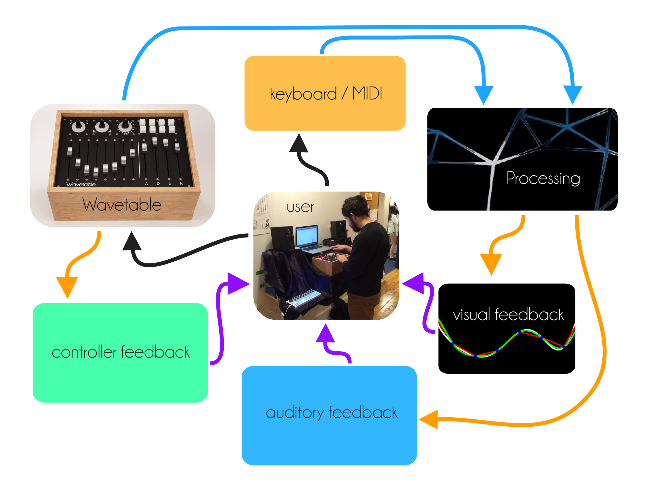 This figure outlines the system diagram for the synthesizer. Parameters from the wavetable controller and midi note values meet in the processing sketch, which provides auditory and visual feedback.
SOFTWARE SYNTHESIS
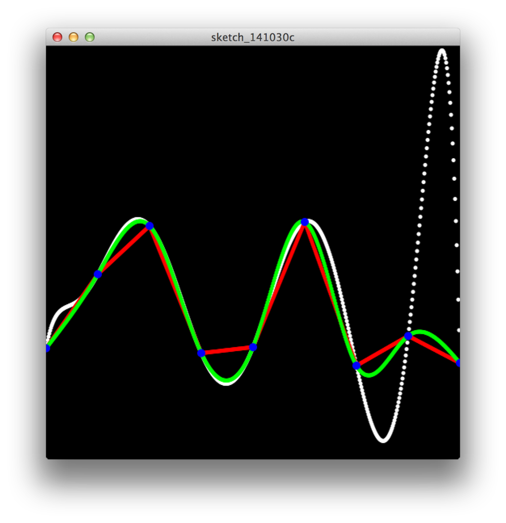
The software for the Wavetable is where all sound synthesis takes place. Due to familiarity and available resources, Processing (Java) was used. The first challenge in creating the software was to create a smooth waveform from only eight distinct points. In order to accomplish this, an interpolation function needed to be utilized. While the math to perform these interpolations is readily accessible, Java also has libraries available to aid in this. The image to the right shows comparisons of the Apache Lagrange (white), spline (green), and linear (red) interpolations. Ultimately, the spline and linear interpolations were used in conjunction with a “square wave” interpolation.
In order to then play the waveform, the minim wavetable function was implemented. The MidiBus library handled all midi communication.
The processing code can be download here
UNDER THE HOOD
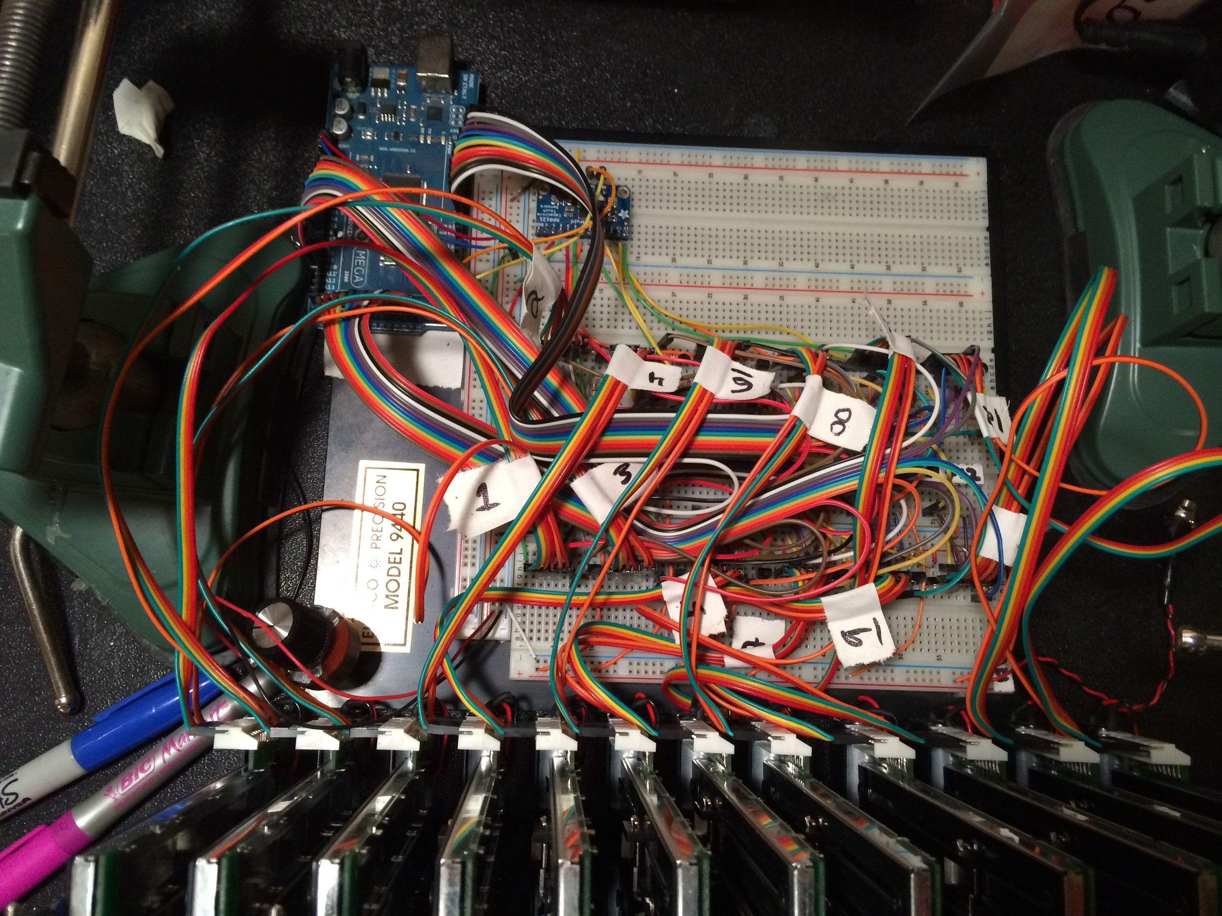
The brains of the controller is an Arduino Mega 2560. Code for the project can be downloaded here.
FLYING FADERS
In order to have the linear potentiometers react to the presets called, motorized potentiometers AKA “flying faders” were used. Each potentiometer features a DC motor that can control the fader position. These motors require an H-bridge to function, which in turn require two digital pins and a PWM pin from the Arduino to vary motor speed and direction. Since this configuration would necessitate an additional Arduino, a transistor was used so that only one enable pin was needed. (see here)
CAPACITANCE
Flying faders would be self defeating without a method to detect touch. Fortunately, motorized potentiometers come with a built in capacitive sense track. When used with metalized fader knobs, touching the knobs can be sensed. Since the Arduino was already low on pins and capacitive sensing can be somewhat fickle, an off-the-shelf solution was sought in the form of the Adafruit MPR121 capacitive sensor breakout. It communicates with the Arduino via I2C and comes with an Arduino library.
ROTARY ENCODERS
Standard 24 position encoders were used in conjunction with a Sparkfun breakout board. The breakout board also allowed for the use of a RGB LED bargraph to indicate encoder position. Since the breakout board uses two shift registers linked to one another to control the bargraphs, changing the LED display only requires shifting out 16 bits.
PRESETS
Presets are controlled using two 2x2 button pads from Sparkfun. Pressing a button causes it to light up, indicating that that the button was fully depressed. The LED’s are common _ RGB LED’s, and are controlled using one 74HC595 shift register. This was especially convenient because the encoder rings already required data and clock lines and could share them with the 74HC595.
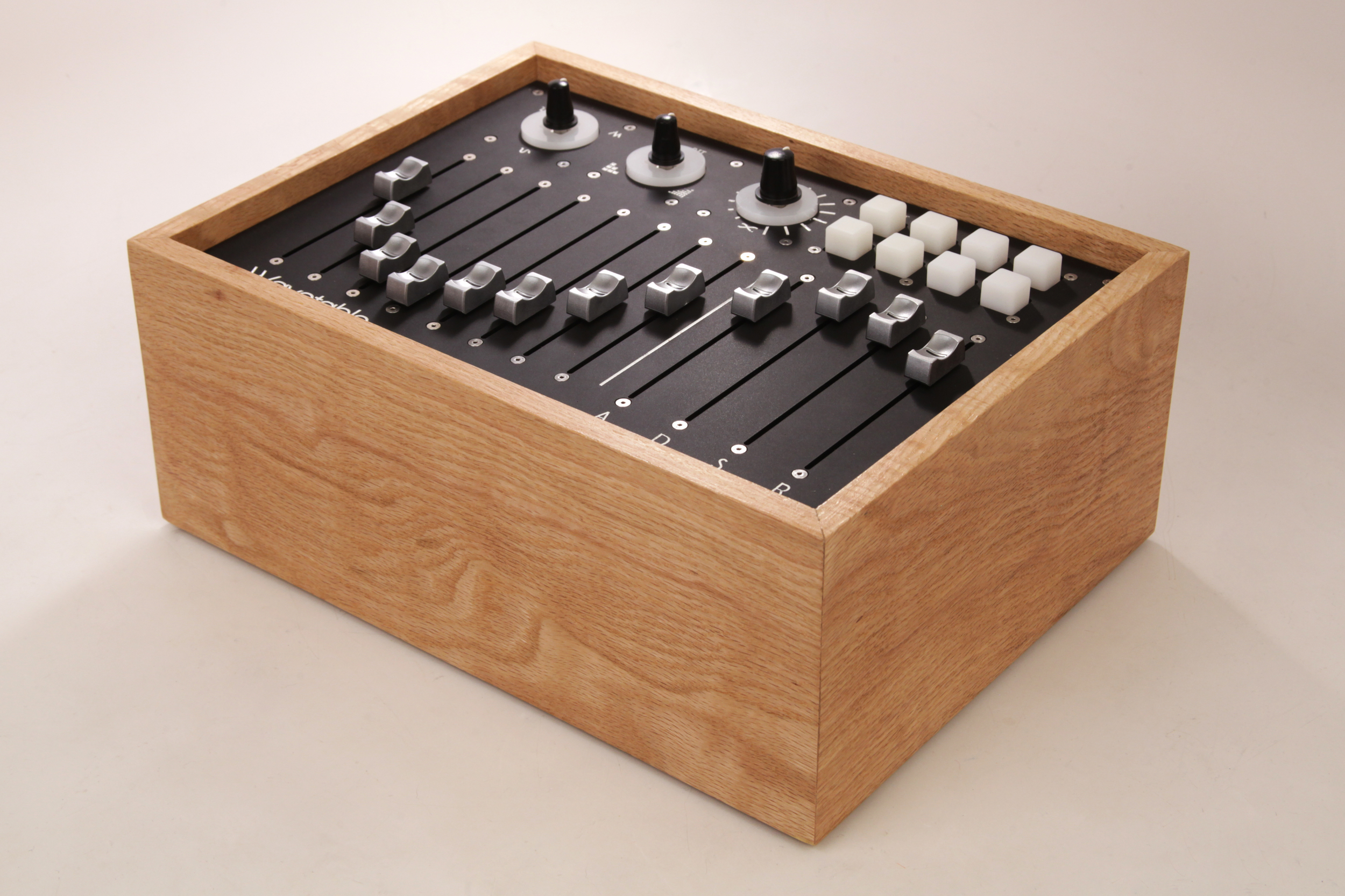
FACEPLATE & EXTERIOR
The faceplate was laser cut from black matte acrylic with white paint-filled lettering. The case was custom fabricated from red oak.
Press
FUTURE PLANS
I’d like to continue working on this project and rebuild the software side in MAX/MSP. Ultimately, it would be great to move away from processing as it is not ideal for sound synthesis. Since I would be programming this in MAX, I also plan to make it a Max for live device. It would be great to be able to distribute it for free and give back to the Max for Live community.
Special thanks to Tom Igoe and Dan Shiffman for their help.